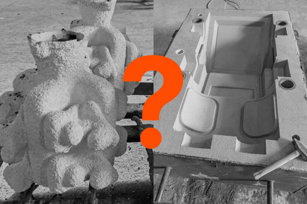
Precision CNC machining drives modern high-performance engineering, transforming digital CAD files into physical reality. It involves removing material with computer-controlled accuracy to create components with complex geometries and strict tolerance adherence, often down to +/- 0.001 inches (0.025mm).
But there is a frequent conflict in this process. It lies between “design intent” and “manufacturing reality.” A file that looks perfect in SolidWorks can easily become a costly failure on the shop floor, driving up costs and extending lead times.
This guide is not a basic tutorial. It’s a technical reference designed for engineering managers and product designers who need to optimize their files for production. At The Federal Group USA, we leverage over 45 years of contract manufacturing experience to help you ensure manufacturability, reduce unit costs, and guarantee that your parts arrive exactly as specified.
Table of Contents
Key Takeaways
- Design for Manufacturing (DFM) is the single biggest lever for reducing CNC costs. Optimizing radii and wall thickness can cut cycle time by 50%.
- Tolerancing strategy matters because moving from +/- 0.005″ to +/- 0.001″ can triple the price of a part.
- Material selection should be driven by machinability ratings, not just mechanical properties, to minimize tool wear.
- Scaling logic dictates when to transition from CNC prototyping to die casting or forging for mass production viability.
- Global logistics and quality control (ISO 9001:2015) are just as important as the machining process itself for reliable supply chains.
Mastering Design for Manufacturing (DFM) Rules

Design for Manufacturing (DFM) is not just about making “good” designs – it’s a rigorous cost-control mechanism. When we review engineering drawings at The Federal Group USA, nearly 30% of “no-quotes” or significantly high cost estimates stem from three specific design oversights.
By addressing these issues before you export your STEP or IGES files, you save time during the quoting process and money on the final invoice.
Understanding Standard vs. Tight Tolerances
Tolerancing is the most direct driver of manufacturing cost. In the CNC machining process, “Standard” tolerance typically refers to +/- 0.005″ (0.13mm). This is achievable with standard cutting speeds and feeds. “Precision” or “Tight” tolerance refers to +/- 0.001″ (0.025mm) or tighter.
Achieving tight tolerances requires slower feed rates, specialized tooling, and often temperature-controlled environments to prevent thermal expansion. So if a feature doesn’t interact with another part, don’t over-tolerance it.
Tolerance (+/- inches) | Relative Cost Factor | Manufacturing Impact |
0.030" | 1x | Standard roughing pass. Very fast. |
0.010" | 1.1x | Standard finish pass. |
0.005" | 1.5x | Standard Precision. Requires careful setup. |
0.002" | 2.5x | High Precision. Slower feeds required. |
0.001" | 4.0x | Critical Precision. Requires specialized tooling/QA. |
Corner Radii, Fillets, and Tool Access
A CNC milling machine uses a round, rotating cutter. That means it can’t create a perfectly square internal corner. When a designer specifies a square corner in a pocket, we have to use Electrical Discharge Machining (EDM) or a specialized broaching process, which adds significant cost.
To optimize for machining, always include a radius on internal vertical edges. The “Golden Rule” is to keep the internal corner radius at least 1/3 of the cavity depth (a 3:1 Depth-to-Diameter ratio) as this prevents tool deflection. If the tool is too long and thin, it will vibrate (chatter) against the metal, leaving a poor surface finish.
Wall Thickness and Feature Geometry
Thin walls are a primary cause of part failure during machining. As the cutter removes material, it applies pressure to the workpiece. If the wall is too thin, it acts like a reed and vibrates. This causes chatter marks and creates dimensional inaccuracies.
We recommend adhering to specific minimums based on the material’s rigidity:
- Aluminum/Metals: Absolute minimum of 0.020″ (0.5mm), though 0.040″ is safer.
- Plastics (Delrin/ABS): Absolute minimum of 0.040″ (1.0mm) to prevent warping from heat buildup.
Also, keep in mind that metal has internal stresses. When you machine away the outer layers of a block to create a thin wall, those internal stresses release, causing the part to warp or bow out of tolerance.
Feature geometry also extends to holes and edges. Always design holes based on standard drill sizes to avoid custom tool charges. For threaded holes, we often recommend thread milling vs. tapping in harder alloys to minimize the risk of tap breakage inside the part. Finally, include specific 0.010″ break-edges or chamfers and deburring notes on your print to ensure safe handling without requiring a manual filing process.
Material Selection: Balancing Cost and Performance
Choosing the right alloy is about balancing mechanical requirements with “machinability.” Machinability refers to how easily a material can be cut. We rate Aluminum 6061 as the baseline (100%). Harder materials like Stainless Steel or Titanium take longer to cut and wear out tools faster, driving up the unit price.
Use this matrix to validate your material choice against your budget.
Material | Cost Factor | Machinability Rating (%) | Strength | Corrosion Resistance | Best For |
Aluminum 6061 | Low | 100% (Baseline) | Medium | Good | General purpose, brackets, housings. |
Aluminum 7075 | Medium | 80% | High | Fair | High-stress structural aerospace parts. |
Stainless Steel 304 | Medium-High | 45% | High | Excellent | Medical devices, food processing. |
Stainless Steel 316 | High | 40% | High | Superior | Marine environments, chemical processing. |
Titanium Ti-6Al-4V | Very High | 15-20% | Very High | Excellent | Aerospace, medical implants (lightweight). |
Delrin (Acetal) | Low | 140% | Low | Good | Low-friction bearings, insulators. |
Surface Finishes and Post-Processing Standards
The “As-Machined” finish is the most cost-effective state for a part. It typically leaves a surface roughness of Ra 3.2 μm (125 μin) and visible tool marks. For internal components, this is usually sufficient. But for consumer-facing or high-wear parts, post-processing is necessary.
Choosing a finish isn’t just about aesthetics, though – it also changes the dimensions of the part. Anodizing, for instance, adds material thickness. If you have a +/- 0.001″ tolerance on a bore, you must account for the anodized growth layer in the machining stage, or the final part will be out of spec.
Finish Name | Appearance | Ra Value (Typical) | Cost Impact | Best Application |
As-Machined | Visible tool marks, shiny. | 3.2 μm (125 μin) | Low | Internal brackets, non-aesthetic parts. |
Bead Blast | Matte, uniform texture. | 1.6 - 3.2 μm | Low-Medium | Removing tool marks, visual uniformity. |
Anodize Type II | Colored/clear, matte or semi-gloss. | Changes by < 0.0005" | Medium | Corrosion resistance, cosmetic color. |
Anodize Type III | Darker, "Hardcoat." | Changes by ~0.002" | High | High-wear surfaces, extreme durability. |
Powder Coat | Thick, paint-like layer. | N/A (adds thickness) | Medium | Outdoor durability, specific branding colors. |
Scaling Production: When to Move From CNC to Casting
One of the most common pitfalls we see in engineering is the failure to transition processes as volumes increase. Engineers often stick with CNC machining for thousands of units because that was the process used for the prototype. This kills profitability.
CNC is a subtractive process because you pay for the material you remove. Casting is a near-net-shape process, so you only pay for the material you use.
At The Federal Group USA, we act as your engineering partner rather than just a machine shop. A local job shop that only owns CNC machines will likely quote you for 5,000 machined parts because that is the only tool they have. We look at the volume and say, “It’s time to invest in tooling.” By moving to investment casting or die casting, we often reduce the per-unit cost by 40-60%, amortizing the tooling cost quickly over the production run.
Use this comparison to decide when to switch:
Process | Best For (Volume) | Tolerance Capability | Setup Cost | Unit Cost @ Volume |
CNC Machining | Low (1 - 500) | Highest (+/- 0.001") | Low (No tooling) | High |
Investment Casting | Medium (500 - 5,000) | High (+/- 0.005") | Medium | Medium |
Die Casting | High (5,000+) | Medium (+/- 0.005") | High (Hard tooling) | Lowest |
Quality Control and Global Logistics
In contract manufacturing, trust is built on verification, not promises. The distance between a factory floor and your receiving dock can introduce risk if not managed with rigorous oversight.
Quality control must go beyond a simple “pass/fail.” It requires documented proof that the metal composition matches the ASTM standard and that critical dimensions meet the print. At TFG USA, our on-the-ground staff utilizes CMM (Coordinate Measuring Machine) inspections to verify complex geometries that hand calipers cannot reach.
Beyond quality, there is the headache of logistics. Manufacturing parts globally often involves navigating customs, freight forwarders, and warehousing. We handle the entire manufacturing process so that you don’t need to worry about Incoterms or shipping delays. You simply receive the inspected parts at your facility, ready for assembly.
Ensuring Success in Your Next CNC Project

Great parts start with great data. The difference between a seamless production run and a manufacturing disaster often comes down to the details in the CAD file, specifically the corner radii, wall thickness, and chosen tolerances.
But even the best file needs a capable partner. Understanding DFM rules is critical, but the key to scalable success is partnering with a manufacturer who understands the entire lifecycle – from prototype optimization to global logistics.
If you are ready to validate your design, submit your drawings for a DFM review. Let’s ensure your project is built to print, on time, and on budget.
FAQs
What is the most cost-effective material for CNC machining?
Aluminum 6061 is generally the most cost-effective metal. It has a high machinability rating, meaning it cuts fast and causes minimal tool wear, keeping cycle times low. For plastics, Delrin (Acetal) is the most machinable and stable option.
How can I reduce the cost of my CNC-machined parts?
You can reduce costs by loosening non-critical tolerances (e.g., +/- 0.005″ instead of +/- 0.001″), adding internal corner radii to allow for larger tools, and minimizing the number of setups required (avoiding designs that need machining from 6 different sides).
For a more detailed explanation, read our article on the cost of CNC machining.
What is the difference between 3-axis and 5-axis machining?
3-axis machining moves the tool along the X, Y, and Z axes – the part stays stationary. It is cheaper but requires manual flipping for multi-sided parts. 5-axis machining moves the tool and rotates the part simultaneously, allowing for complex geometries and machining up to 5 sides in a single setup, which improves accuracy.
Does The Federal Group USA handle international shipping for parts?
Yes. We provide end-to-end project management. This includes managing production, quality, handling all customs and duties, and arranging freight to your door. You deal with a domestic partner while accessing global manufacturing economics.
What file formats are best for CNC quoting?
For quoting and manufacturing, a 3D STEP (.stp) file is the industry standard because it contains precise geometry data. A 2D PDF drawing is also required to specify tolerances, threads, and surface finishes that the 3D model does not explicitly show.
Richard Jegla
Sales Engineer
Richard has been on The Federal Group team for 24 years and his knowledge spans a variety of mechanical engineering topics. When he isn't assisting his clients, he is routinely working on his motorcycles and off-road vehicle projects.
Up Next

